Verilog TUTORIAL for beginners
We hope that, before you read this tutorial, you have downloaded the Xilinx ISE free version - which, we will use to learn verilog. It has a nice in built simulator as well. If your download is not yet finished, do not worry, and continue to read the tutorial. You will still have a good understanding of the verilog concepts.
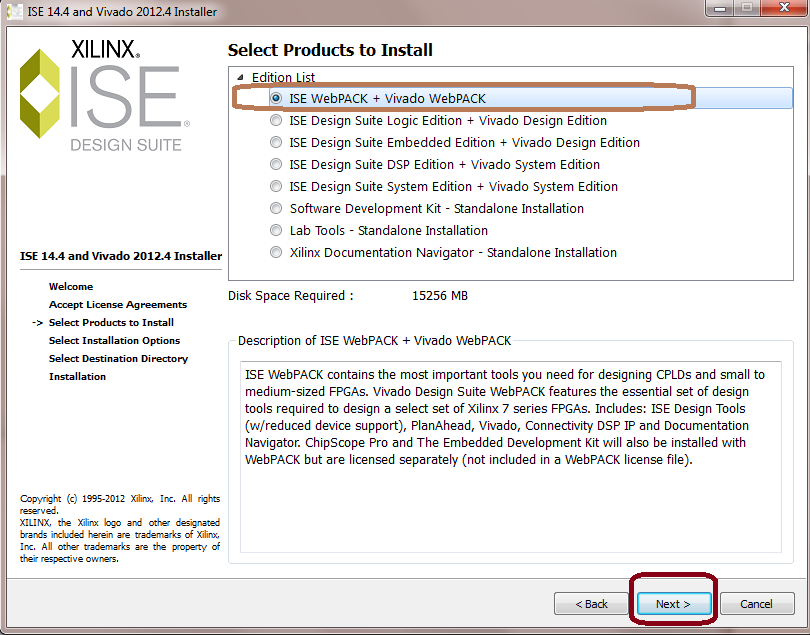
Once the download finishes, install the Xilinx ISE. There are two things that require attention.
1. Choose the ISE Webpack+Viviado Webpack for installtion. This is the free version. Others are paid versions.
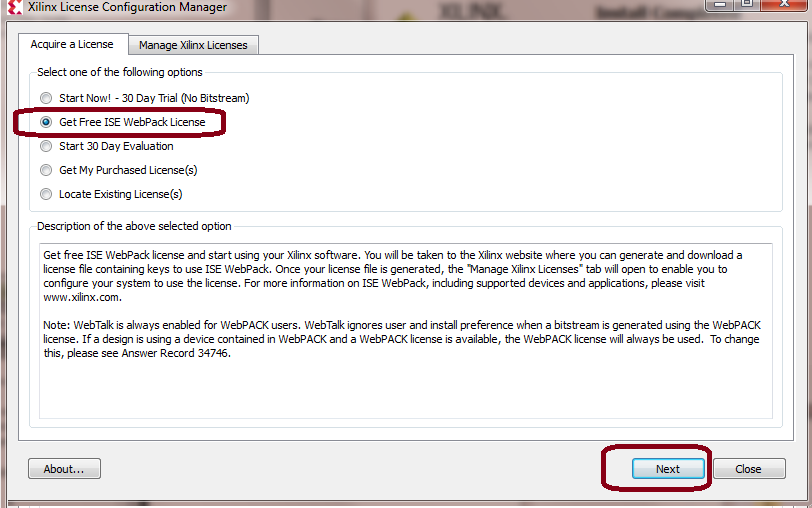
2. Once you finish the installation, you will be asked to register to get the license. When appling for the license you need to select "Get Free ISE Webpack License".
This will complete the installation. We will now start learning the Verilog itself. Notice that you can follow this tutorial even if you have not installed the tool, but it is a good idea to practice by writing, compiling and running the actual verilog code.
Let us start with the design of a simple comparator. This will also be our "Hello World" of the Verilog. Let us take a look at the following table which describes the behavior ( We are using American spelling behavior in place of behaviour - sorry about that) of a comparator circuit.
Table: A one bit comparator
| Input x | Input y | Output z |
| 0 | 0 | 1 |
| 0 | 1 | 0 | 1 | 0 | 0 |
| 1 | 1 | 1 |
Basically when both the inputs x and y are same, the output z is 1. When the inputs are unequal, the output is 0.
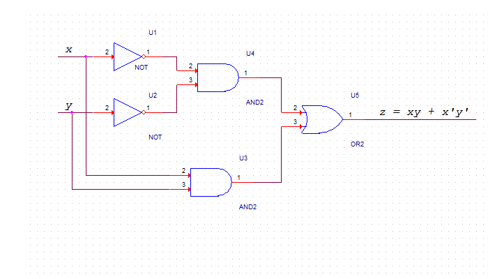
We can describe the circuit using AND , NOT and OR gates using the following equation.
assign z = (~x & ~y) |(x & y);
where ~x and ~y represent the complements of x and y respectively.
The following shows a circuit that implements this logic.
And here is the verilog code that implements this logic
|
We will try to make you understand what Verilog is - in a matter of one day. At least you should be able to compile and run verilog code ( Kind of Hello World of verilog). We hope that this is something you will be able to achieve within next few pages. Throughout this tutorial, we will present you enough examples and exercises so that you have a good grip over the language as well as the verilog concepts.
While Verilog has concurrent blocks executing in parallel, it is still similar to software programming language like C.
If you have closely watched the schematics above and the verilog code below it, you must have appreciated how verilog simplifies the process. Before the advent of Verilog, everything was done using schematics. The schematics were error-prone, difficult to verify, and had long process of design, verfification, fix, redesign and re verify and so on.
With Verilog, the whole dimension and process of hardware circuit design changed. This provided a new way of looking at designing the circuiy. Verilog design is more like a software programming, but, you must also have a strong understanding of the circuit that works behing the code.
Let us now understand the code. Take a loook at
|
Verilog consists of modules. Inside the modules, we have a list of ports ( or pins). A port can be an input port or an output port depending upon its direction. A pin can also be defined as bidirectional using inout.
The direction can also be specified out of the module. This code is equivalent to the previous code. In Verilog 1995, this was the only option. The Verilog 2001 allows port direction to be defined with the module declaration itself.
|
Let us now take a look at the assign statement
assign z = (~x & ~y) |(x & y);
This assign statement implements a combinational logic. An assign statement is used for modeling only combinational logic. The statement in the assign statement is executed continuously ( as against those that trigger on a clock). An assign statement is also called 'continuous assignment statement'.
This statement implements the comparator logic that we had shown earlier in the schematics.
In the next page we will see how to test this code using the simulation.