Verilog TUTORIAL | Verificatiom
Now we have understood the concept we will compile the code and run the test bench in Xilinx. If you do not have installed Xilinx, you should still be able to make out what the code does. We have put up everything is a youtube video that you can see.
The steps followed are as follows
1. Create a new project using File -> New project
2. In the project settings, Xilinx require that you fill out the Family, Device, Package and speed.( They want you to use their chip and that is the reason they provide this tool free). For tihs tutorial fill the Family as Spartan 3E, Device as XC3S500E, Package FG320 and Speed -5.
3. Select the project name ( In our case the project name is comparator), right click and click on Add new source -> Verilog Module.
4. In the next screen it will ask for port names. For our example enter x and y against input ( in two different rows), z against output.
5. When you click finish verilog generates a default code that includes module name and input output declaration.
6. Now add the assign code inside the generated code
assign z = (~x & ~y) |(x & y);
Save the file
7. Next we will add the test bench to this code. Select Simulation under the design.
8.Select the project -> Add new source -> Verilog Test Fixture.Enter a file name ( we used stimulus).
9. When you click finish, it generates some default code, to make our life easy ( or make it difficut for us to learn the things by not allowing us to know what it means). Add the stimulus codes that we presented in the previous page. Save the file.
10. Now click on the ISIM Simulator -> Simulate Behavioural Model. Wait for few seconds. If there are no syntax errors it will generate a new window that will display the waveform in the ISIM waveform viewer. Look at the console of the ISIM Viewer - it will show the input and output values of of x, y and z at different times.
As you can see, the simulation produces the following output.
x=0,y=0,z=1
x=1,y=0,z=0
x=1,y=1,z=1
x=0,y=1,z=0
You may want to change the equation to see if the result produced is different.
Exercise
Here is a simple exercise for you.
1. Take a look at the circuit below
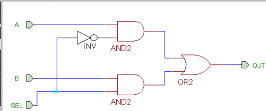
implemment this in Verilog. The module will have three inputs ( a, b and sel) and one output ( out).
2. Write a test bench for the above Verilog and verify that the output is as expected. The output should be something similar to
a=1,b=0,sel=0,out = 1
x=0,y=0,sel=0,out = 0
In the next page we will learn more about Verilog and its language construct.