Kicad Schematics TUTORIAL
The Design Objective
The purpose of this particular tutorial is to draw a schematics of the following Circuit in KiCad.
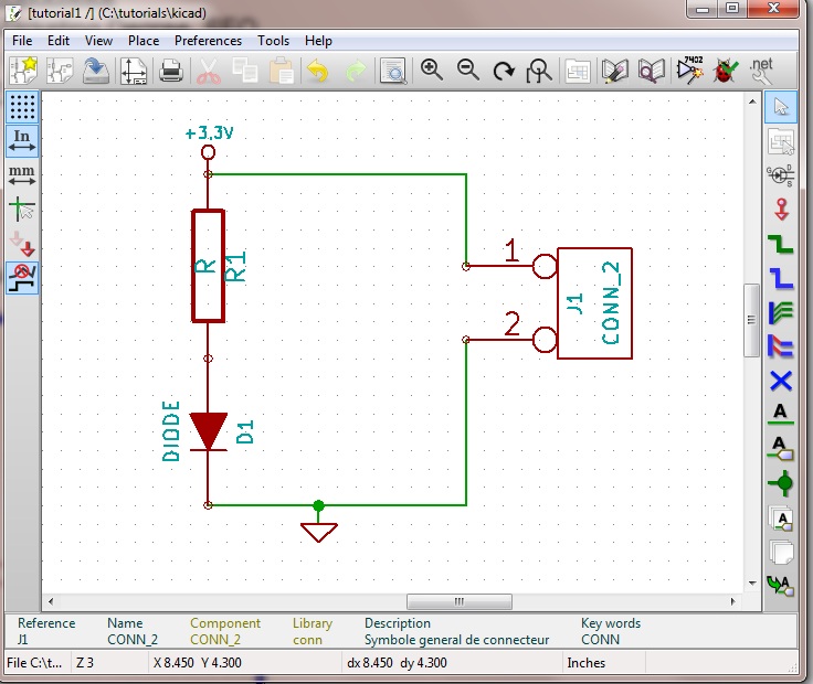
* This is essentially very simple circuit. Its functionality is to make an led D1 glow when a Power Supply is connected at the connector J1. This is a "hello world" of the and electronics design. Our purpose here is not to learn Electronics Design - but to learn - a Schematics Capture Tool.
* As shown in the Schematics, the circuit uses three components - A resistor, A connector and an LED ( or a Diode Rather)
R1
J1
D1
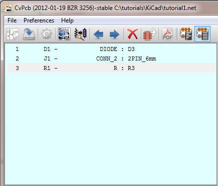
* Each component will have an associated footprint. We have given the followint names to the footprints of the components used.
In the next few pages we will place these three components.