Op Amp Tutorial for beginners
This tutorial by ReferenceDesigner.com is intended for students enthusiasts and electronic designers who wish to learn about Op Amp. The material presented here can also be used as a reference material by experienced designers.
Introduction
An Operational Amplifier, or Op-Amp for short, is an abstraction at physical level as well as conceptual level.
At physical level, an Op-Amp comes as an integrated circuit and is fabricated from several hundred basic building blocks such as FETs, resistors etc. It comes as an integrated circuit with single, dual, quad or more op amps in a single IC, and can be purchased for as low as 10 cents. You do not need to worry about what in inside the IC or what circuit makes the Op Amp, as long as you understand the basics of how the Op-Amp functions. This is what we mean by abstraction of Op Amp at physical level. As an example the Texas Instruments' LM741 is a general purpose amplifier. You can check its details at TI website here .
At conceptual level, you need to understand the black box function of an Op Amp. You do not worry about how the internal circuit of the Op Amp functions. We need to know the properties of the Pins of the Op Amp and then, we can create hundreds of useful circuits based upon the understanding of these abtractions at conceptual level.
To give you an analogy of Op-Amps with software world - Op-Amps are the fuctions or the library of the software world. Once the library is tested and verified, you do not need to worry about the details inside the libraary. For example, once we know how to use printf in C programming language, we need not to worry about the details inside the printf which is actually very detailed and lengthy, but again from usage perspective, it is very easy.
An Op Amp, is represented as a triangular structure with typically 5 terminals as shown in the diagram below. There are two input terminals ( a positive and a negative) and an output terminal. It also has two power terminals - a positive and a negative terminal.
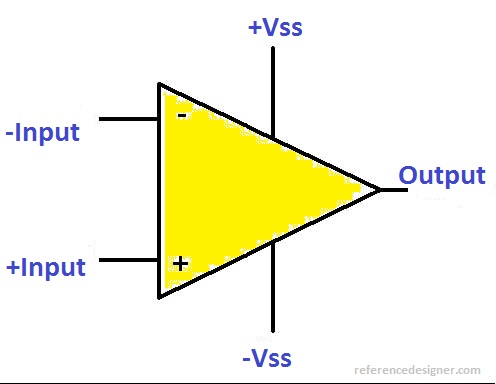
The +Vss and the -Vss connect to the positive of a supply and the negative of another supply. The Output of the OP Amp can not go beyond the +Vss on the positive side beyond -Vss on negative side. Often the supply terminals are also not explicitly shown in Op Amp but is present there as in the following diagram.
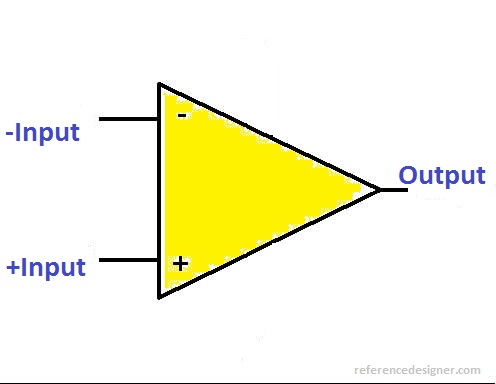
We will be using these symbols over and over, again and again. You do not need to memorize it - it will automatically settle in your mind as you go through the tutorials presented.
An Op Amp has few basic characteristics
1. It has practically infinite input resistance. It basically means that there is practically no current flowing in the Op Amp. This has very important implication, as we will see in the analysis of the circuits in the next few tutorials.
2. The Op Amp amplifies the difference in between its two input terminals and has a very high gain. If v+ and v- are the voltages at the two input terminals of the Op Amp, then the output is given by
vout = A (v+ - v-)
where A is called the open loop gain of the Amplifier which is typically very high ( something like 10,000). An open loop is formed when neither of the inputs is connected in feedback ( with the output). We will learn about the feedback ( an important concept later on).
3. An Op Amp has a very low ( practically zero) output impedance.
In the next page of the tutorial we will see what happens when we connect the Op Amp as a difference amplifier ?