Pspice TUTORIAL
We will start with something really very basic. Its purpose is not to equipt you with any expertise in spice but rather to make sure that the system and the set up are working.Aim
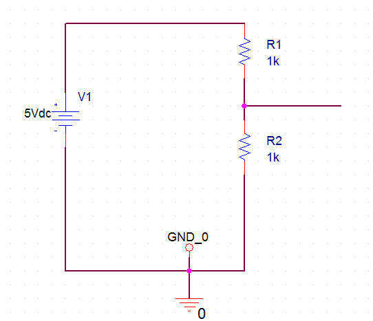
Out tartget is very simple. We want a very simple circuit with a 5V DC source and a pair of resistors conneted to the voltage source. We wish to find the voltage at the junction of the two resistors, which we know is going to be 2.50V. The circuit looks as follows.
To do this follow the following steps 1. Open orcad and click on File -> New -> Project. Give a name to project and select "Analog or Mixed A/D". We can start with an existing project or create a blank project. For this project we will just select the default AnalogGNDSymbol.opj which just adds a Ground on the project.
2. Next we will add two resistors of value 1k and place them on the canvas. Click on Place -> Parts -> Select Analog in Libraries and select R in Part. Place the two resistors. You can change the values of the resistors by double clicking these. To rotate the resitors press R while the resistor is selected. Join the resistors using place wire. Connect one edge of resistor to the ground.
3. Next place a voltage source and assign it 5V DC. To do this click on place parts -> Select "Source" in Library and VSRC in part. Connect the positive edge of the voltage source to the resistor and the negative edge to ground. Double click the voltage source and set its DC value to 5.
4. Next place voltage level markers at the positive end of the voltage source and at the junction of the two resistors.
5. Open the PSpice menu and click on Simulation Profile. Left-click on it and in the next window give a name to the simulation. In the next window select "Bias Point" as the type of simulation in the Analysis Tab.
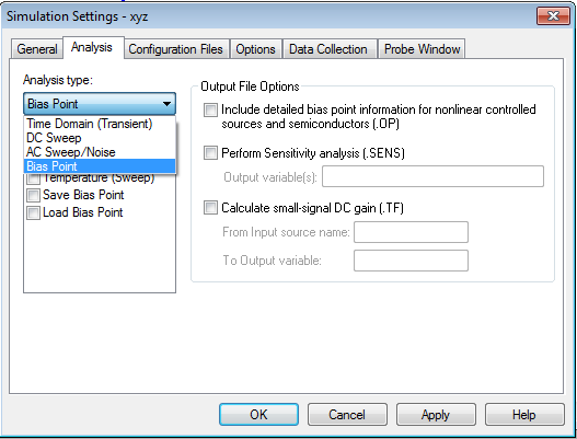
There are three more types of Analysis - DC Sweep, AC Sweep and Time Domain. We will go through theses in next few tutorials. For now we would start with simplest of these - DC Bias Point.
6. Next Click on Run PScpice. If there are no connection or other errors, it will run and show the DC Bias points.
In the video below, we have captured the calculation of the Bias point of the resistor junction.
Exercise
Find the bias point of the Collector of the Transistor Q2 in the following circuit using Orcad Pspice for two different settings of the input voltage V1 = 0V and V1 = 2V
Here is the solution in video format.