Verilog Examples - LED blinkning by clock divider


We will now extend out clock Divide by 2N code to blink and LED. Basically we will set the parameters of the clock divider. We will also examine the issue with large data generated in test bench.


Problem - Write verilog code that has a 50 MHz clock and a reset as input. It has an output that can be called clk_out. The clk_out is also a clock that has a frequency of 2.5 Hz of time period of 400 ms. Extend the parameter to calculate the values for the parameter for 1 Hz clk_out.

Solution -

This is the main code ledblink.v


  1. // LED Blinking Example by Clock Divider
  2. // referencedesigner.com tutorial
  3.  
  4.  
  5. module clk_div
  6. #(
  7. parameter WIDTH = 24, // Width of the register required
  8. parameter [WIDTH-1:0] N = 24'h989680// That is 10,000,000 in decimal
  9. )
  10. /*
  11.  We will divide 50 MHz by 20,000,000
  12. ( We are dividing by 2N - which gives 2.5 Hz signal or time period of 400 ms or half time period of 200 ms
  13. */
  14.  
  15. //Changing N to 25,000,000 or 0x17D7840 will generate a 1 Hz Signal
  16. // Increases simulation time
  17.  
  18. (clk,reset, clk_out);
  19.  
  20. input clk;
  21. input reset;
  22. output clk_out;
  23.  
  24. reg [WIDTH-1:0] r_reg;
  25. wire [WIDTH-1:0] r_nxt;
  26. reg clk_track;
  27.  
  28. always @(posedge clk or posedge reset)
  29.  
  30. begin
  31. if (reset)
  32. begin
  33. r_reg <= 0;
  34. clk_track <= 1'b0;
  35. end
  36.  
  37. else if (r_nxt == N)
  38. begin
  39. r_reg <= 0;
  40. clk_track <= ~clk_track;
  41. end
  42.  
  43. else
  44. r_reg <= r_nxt;
  45. end
  46.  
  47. assign r_nxt = r_reg+1;
  48. assign clk_out = clk_track;
  49. endmodule
  50.  


Here is the test bench ledblinktb.v

  1. `timescale 10ns/1ns
  2. module clkdiv2n_tb;
  3. reg clk,reset;
  4. wire clk_out;
  5.  
  6. clk_div t1(clk,reset,clk_out);
  7. initial
  8. clk= 1'b0;
  9. always
  10. #1 clk=~clk;
  11. initial
  12. begin
  13. #2 reset=1'b1;
  14. #3 reset=1'b0;
  15. #40000000
  16. #20 $finish;
  17. end
  18.  
  19. initial
  20. $monitor($time, " reset=%b,clk_out=%b",reset,clk_out);
  21. initial
  22. begin
  23. $dumpfile("clkdiv2n_tb.vcd");
  24. $dumpvars(1,clk_out); // To reduce file size we are only monitoring clk_out
  25.  
  26. end
  27. endmodule
  28.  
  29.  


The waveform generated by this code is here
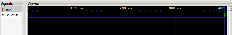


Explanation

The value of the divider 2N to generate 2.5 Hz clock is 20,000,000 which gives N = 10,000,000. In hexadecimal it is 24'h989680. We calculated hex value to find the number of bits required for the register.

module clk_div 
#( parameter WIDTH = 24, 
parameter [WIDTH-1:0] N = 24'h989680
)


In test bench we did monitor clk as it will generate huge output without much value. We can run it just once to make sure that it is 50 MHz. Also note that we have set the timescale to 10 ns which is half clock period.

 $monitor($time, " reset=%b,clk_out=%b",reset,clk_out);


In the $dumpvars we are dumping only the clk_out as in

 $dumpvars(1,clk_out);


If we would have done

 $dumpvars(0,clkdiv2n_tb);


It would have dumped all variables including the clk which will make the size of the dump file unnecessarily large. The reset of the code should be easy to understand