Verilog Examples - Clock Divide by even number 2N
A clock Divide by 2N circuit has a clock as an input and it divides the clock input by 2N. So for example, if the frequency of the clock input is 50 MHz, and N = 5, the frequency of the output will be 5 MHz. In other words the time period of the outout clock will be 2N times time perioud of the clock input.
To generate a clock frequency ny even number you only need to work on the rising edge of clock and hence the circuit is simplified and potentially free from the glitches that a clock divided by an odd number works.
Problem - Write verilog code that has a clock and a reset as input. It has an output that can be called clk_out. The clk_out is also a clock that has a frequency that is 1/2N frequency of the input clock. It has synchronous reset and if there if the reset is 1, the outclock resets to 0. Write test bench to verify it.
Solution -
This is the main code clock.v
|
Here is the test bench clocktb.v
|
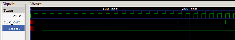
The waveform generated by this code is here
Explanation
We have used two parameters - one is N which defines half the value of the divider. Another parameter WIDTH helps define the register width. The register width depends upon N. It is the minimum number of widths needed to count N. For example if N is 8 ( binary 4'b1000), WIDTH will be 4. If N is 21, WIDTH will be.
module clk_div #( parameter WIDTH = 3, // Width of the register required parameter N = 6// We will divide by 12 for example in this case ) |
We have triggered the always block at positive edge of clock and count up to N and then invert the output clock.
if (r_nxt == N) begin r_reg <= 0; clk_track <= ~clk_track; end |
In the testbench you may try to use a different parameter that will create a different divider when calling module. ( See the exercise below). For example following will divide by 24.
clk_div #(4, 12) t1(clk,reset,clk_out); |
The reset of the code should be easy to understand
Exercize
1. Create a top module that has clk and reset as input and has two outputs call them clk_out1 and clk_out2. The module creates two instances of the clock module clk_div that we created above. One will divide the clock by 10 and other will divide it by 20. Create test bench to verify it.