Timing Control and delays in Verilog |
We have earlier seen how we have used delays when creating a testbench. A delay is specified by a # followed by the delay amount. The exact duration of the delay depends upon timescale. For example, if with `timescale 2ns/100ps, a delay with statement
#50 ; |
will mean a delay of 100 ns.
Delays can also be specified within an assignment statement as in
p = #10 (a | b); // Example of intra-assignment delay |
This statement is interpreted as follows - First evaluate the right hand expression (a | b). Then wait for 10 units of time ( again remember that unit of time is defined in timescale). After this wait, assign the value of RHS to LHS. The above is called intra assignment delay. The above statement is equivalent to
temp = (a | b); // evaluate the RHS and hold it temporarily #10; // Wait for 10 units of time p = temp; // Assign the temporary evaluation to LHS |
Real circuits in ASIC have delays. For example logic gates may have propagation delays associated with them.
Delays for Primitive Gates |
We may specify the Gate Delay as in following example
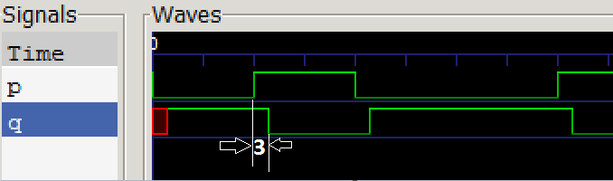
module notgatedelay( input p, output q ); not #3 (q,p) ; endmodule |
The input p will be delayed by 3 units of time through the not gate for both the rising as well as falling edge of the input p. You can see this in the following timing diagram.
Some note on delay and timescale |
iverilog stimulus.v main.v
where file stimulus.v is the testbench containing the `timescale directive and the main.v is the main program. If you however, give the command
iverilog main.v stimulus.v it will report error
found both default and timescale based delays
Typical Min and Max Delay |
We may specify Min, Max or Typical Delay as in
module notgatedelay( input p, output q ); not #(2:3:4) (q,p) ; endmodule |
In the above example the Min delay is 2, typical delay is 3 and Max delay is 4. In Icarus, which delay is to be used, is specified using -T option. For example to run it for min delay we will use the following comman
iverilog -Tmin stimulus.v main.v
Rise and Fall Delay |
It is possible to define the rise and fall delays separately as in follwing example
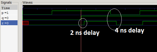
module andgatedelay( input p,q, output r ); and #(2,4) u_and (r,p,q); endmodule |
In this case the rise time delay is 2 units and the fall time delay is 4 units. The two delays are separated by comma as in
and #(2,4) u_and (r,p,q); |
This is the test bench for above code
`timescale 1ns / 100ps module stimulus; // Inputs reg p,q; wire r; andgatedelay n1 ( .p(p), .q(q), .r(r) ); initial begin $dumpfile("test.vcd"); $dumpvars(0,stimulus); p = 0; q =0; #20 p = 1; #20 q = 1; #20 p = 0; #20 p = 1; #40; end initial begin $monitor($time, " p=%1b,q=%1b, r = %1b",p,q,r); end endmodule |
The waveform is shown below