Verilog Multiplexer
| Multiplexer |
We will continue to learn more examples with multiplexer. A multiplexer selects one of several input signals and forwards the selected input into a single line.
A single bit multiplexer will have one control line two inputs ( say X and Y) and one output ( say Z). When the conrols is 0, X is connected to Z. When the Control is 1, Y is connected to Z.
The figure below explains this
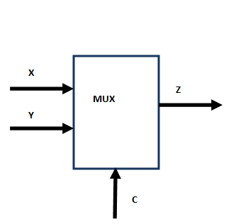
We can extend this idea to increase the number of the control bits to 2. This 2 bit multiplexer will connect one of the 4 inputs to the out put. We will now write verilog code for a single bit multiplexer.
mux.v
|
We have used assignment statement that uses conditional operator
assign out = cntrl ? in1 : in2;
The conditional operator is makes use of ? and. Its syntax is as follows
Conditional Expression? true expression : false expression
The conditional expression is evaluated and and if it is true, the "true expression" else "false expression" is evaluated.
Looking at the example above the cntrl is evaluated and if it is 1, the in1 is assigned to out else in2 is assigned to out.
We will now add a test bench to confirm that the result is as expected. So here goes the test bench.
mux2tb.v
|
As usual we will compile the program with following commands
C:\iverilog\bin\src\mux>iverilog -o output mux2.v mux2tb.v
C:\iverilog\bin\src\mux>vvp output
          	   0 out=0,cntrl=0,in1=0,in2=0
               1 out=0,cntrl=0,in1=1,in2=0
               2 out=1,cntrl=0,in1=0,in2=1
               3 out=1,cntrl=0,in1=1,in2=1
               4 out=1,cntrl=1,in1=1,in2=1
               5 out=0,cntrl=1,in1=0,in2=0
               6 out=1,cntrl=1,in1=1,in2=0
               7 out=0,cntrl=1,in1=0,in2=1
               8 out=1,cntrl=1,in1=1,in2=1
1. Extend the multiplexer with 2 control bits and 4 inputs.
| Solution |
Before looking at the solution, make sure you have given your efforts to solve it. Here are the solution codes.