MSP430 Embedded Programming Tutorial TUTORIAL
An LED ON and OFF Program
The first thing we will do is replace the include file io430.h in main.cpp with the file that correspond to the microcontroller that we are using. In our case it is io430x14x.h. You may like to browse throught the directory
C:\Program Files\IAR Systems\Embedded Workbench 5.0\430\inc\
to check which include file needs to be used. Note that io430x14x.h corresponds to MSP430F149. This file contains the definitions of all the ports and memory locations. You may like to take a brief look at this file for now. You will need to refer this file many times in future. This is an important include file.
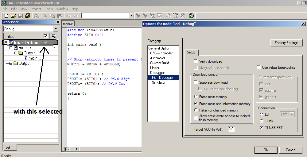
We will be using the Emulator instead of Simulator. With the first row in the Files selcted( that is the project name), select Project -> Options. Select Debugger, and in the Setup -> Driver select Fet Debugger.
Here is how it will look like
Now add the following code
|
#include <io430x14x.h> #define BIT0 0x01 int main( void ) { // Stop watchdog timer to prevent time out reset WDTCTL = WDTPW + WDTHOLD; P6DIR |= (BIT0) ; P6OUT|= (BIT0) ; // P6.0 High P6OUT&=~(BIT0); // P6.0 Low return 0; } |
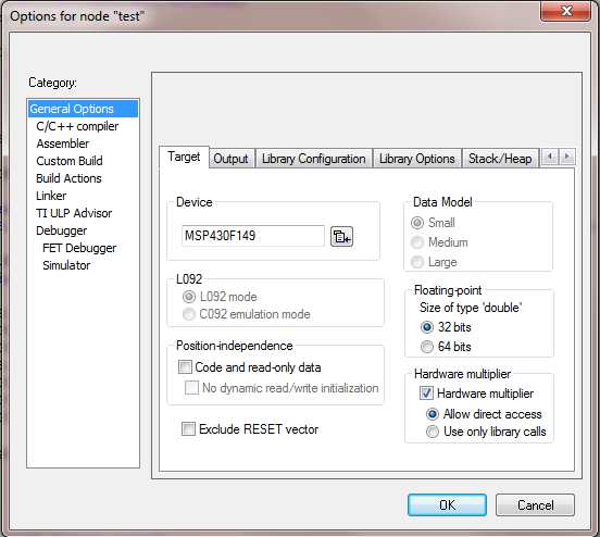
You should also select the right device. This can be done using Projects -> Options -> general options -> Target -> Device. Select the device on your hardware.
This is the "Hello World Program of the Microcontroller world. What will this program do ? This program will give a low output on the port pin P6.0 and thereby make the LED glow.
Compile this program using F7 button.Make sure you have no errors. Now Press Control-D with the emulator and the board connected. This will download the program to the evaluation board containing the LED. Run this program by pressing F5. You will observe that the LED is glowing.
Understanding the Program
We are trying to make a pin of MSP430 as an IO Port. The Port Pin is P6.0. Any IO pin in the microcontroller can be used either as an Input Pin or as an Out pin. The P6DIR defines the direction of the port pin. The statement
|
P6DIR |= (BIT0) ; |
states that the port pin P6.0 is an out put pin. Similary, the statement P1DIR |= (0x04), will assign P1.2 to be an output pin. P1DIR is defined in the file io430x14x.h. You may like to open this file and search for P6DIR. You will notice that it corresponds to the memory location 0x036. You may now like correlate it with the memory map of the MSP430F149. If you look at the datasheet of MSP430F149 you will find that the direction of PORT6 is defined at memory location 0x036.
Now take a looks at the staement
|
P6OUT|= (BIT0) ; // P6.0 High |
The statement
|
P6OUT&=~(BIT0); // P6.0 Low |
This statement will make the P6.0 pin to low. If your hardware was connected as as shown in Page 2 of the tutorial, this will make the LED go on.
You you write the program as
|
#include <io430x14x.h> #define BIT0 0x01 int main( void ) { // Stop watchdog timer to prevent time out reset WDTCTL = WDTPW + WDTHOLD; P6DIR |= (BIT0) ; P6OUT&=~(BIT0); // P6.0 Low P6OUT|= (BIT0) ; // P6.0 High return 0; } |
and run it using F5, the LED will go off.
This simple program will familiarise you with the set up and environment. Now take a coffee break before we proceed further.